Breadboard
The next thing I did was to create a breadboard on which all electrical components are placed. The main purpose is to check the electronics, and then to see if I can create a simple design (i.e. a rectangle), create the G-code, upload it to the Arduino and see if the steppers move as expected. This is a nice way to check that everything works before committing to a complete build and possibly finding out that something is missing.
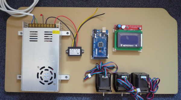
An old board was used to hold all components:
The RAMPS board is not yet plugged into the Arduino board, I read on the v1engineering website that the firmware for the Arduino board should first be uploaded before the RAMPS board is installed.
The first thing to test is the power supply (of course). Some switching power supplies can be a bit fickly concerning their output, that is, they should not be switched on without any load. I was not sure about this power supply, so just to be safe a common 3mm red LED (including limiting resistor) was attached to the output before switching it on.
A LED has a polarity and should be connected correctly: minus to minus, plus to plus. The flatted side of a common 3mm LED is the minus lead. It should be attached to the minus pin of the power supply. The plus lead of the LED is soldered to the current limiting resistor and the other lead of the resistor is attached to the plus of the power supply output.
Most common 3mm LEDS can handle 20 mA just fine. To keep it safe 10 mA is targetted. Since the output is 24 Volts, this yields: 24 V / 10mA = 2400 Ohm. The current limiting resistor thus should be around 2k4 Ohm. I had a 2k7 on my bench, so that is what I used. (Btw I choose to ignore the voltage drop over the LED, it really does not matter here)
Next attach the wires that connect the power supply to the mains. Make sure to attach the ground lead as well (and use a grounded outlet!). Statistically, you will live longer if you ground everything…
I made sure the power supply is in a safe position and then plugged the connector into the mains. The LED came on as expected. Before doing anything else, make sure the metal of the power supply is not connected to the mains. I used a screwdriver voltage pen.
Then measure the output of the power supply with a voltmeter, it is expected to be 24V. Mine was a little high at 25V, but that will probably fall a little under a heavier load, so this is fine.
Then I connected the 24/12 voltage converter (this is the situation shown in the picture). Initially the converter did not work, but after I disconnected and then reattached the wires it worked fine. Probably a bit of oxide that was removed by the mechanical abrasion.
Next is the test of the Geekcreit ATMega2560 development board. The website of the company were I bought the board specified that when the board is connected to a power supply, a LED on the board should start blinking. For this I needed a plug that I forgot to order and is thus not present on the component list in an earlier post. Luckily I had a universal power adapter at hand, and it had the necessary plug and power settings. When I connected power to the ATMega2560, a led did indeed start blinking. Note: Once the RAMPS board is added, the Arduino board will be powered via the RAMPS board and the extra power supply and plug are not needed.
(Though there are reports that the power supply through the RAMPS board is insufficient to drive the backlit LCD screen… I will have to wait and see if that is indeed the case)
Alternatively the board can also be powered via the USB connector, but when the board is attached to the USB connector of a computer, a few more leds will start blinking for a short while.
The next step is to install the CNC driver on the Arduino board. Which I will detail in the next post.