Installing the RAMPS board
Next the RAMPS board needs to be installed in the Arduino board.
Of course we will be doing this while the Arduino board is unpowered.
Before pushing it on, make sure the pins on the RAMPS board are all perfectly aligned. If a pin is out of line, gently push it back. Once all pins are aligned, gently, but firmly push it on the Arduino board.
Next the drivers should be installed on the RAMPS board, but before that the microstepping jumpers have to be configured since these will be unreachable when the drivers are installed.
Note: Do not glue the cooling fins on the drivers just yet.
The purpose of my CNC will be to cut wooden parts from soft wood and plywood (layered wood) an accuracy of 0.1mm is enough. However cutting a curve with 0.1mm steps created a very rough shape, and even if it is accurate enough, I want to do one better and create a smooth curve. Therefore I want a resolution of minimal 0.05mm on the movement of the cutting tool.
The NEMA 17 motors have 200 steps per revolution. They drive a lead screw that has 8 mm travel per revolution. Hence one step is about 8 mm / 200 = 0.04mm tool movement. Which is even better than the resolution I wanted. So it would seem that microstepping is not needed.
However, microstepping smoothens the motion of stepper and stages, reducing wear and tear on the mechanics, and reducing noise and vibration. For this reason microstepping is advisable. How much microstepping? I have not found a very good answer on this. It would seem to me that going for the highest possible number may not be the worst approach.
The DRV8825 driver that I am using supports 32 microsteps. So that is what I will be using. This calls for the first and last jumper in the jumper field below the steppers to be inserted. The middle position does not really matter, either insert a jumper or leave it empty. The result should be the same.
Now it is time to put the drivers in, this is a bit … well, not so easy I found. When you simply use your thumb or fingers, chances are the driver will end up angled. Besides, you should try to avoid touching the driver chip since the fins must be glued onto this surface. So don’t use you fingers, but use a narrow, longish piece of wood (as narrow as the driver is long, and a total length of about 10-20 cm).
Also, the width of the pins of the driver may not align exactly with the row of sockets in which they should be pushed. In this case put the driver sideways on a flat surface and GENTLY apply some force on the pins to ensure a good fit. Then place the pins of the driver on the sockets. Place the longish piece of wood with one end on the driver and the other end sticking out. Put your thumb over de driver and grab the other end of the piece of wood with your free hand. With your free hand make sure the force that is exerted by your thumb stays level. The driver should slip in without much problems. If you encounter real resistance, make sure none of the pins is bent out of place.
Now glue the cooling fins on the driver IC. I made an error and glued it on in the wrong direction. Oh well.. I will pay more attention next time..
Note that cooling paste/glue can be used. But my fins had a sticker to peel of before glueing them on. I thus only used cooling paste (for thermal conductivity) around the very edge of the fins, not on the glue itself!. Needless to say, I used only very very little cooling paste. Hardly anything at all.
Note: Just for completeness, older versions of the Marlin driver SW also required a thermistor (or simply a resistor) to be connected to the board. I do not know which version no longer needs that resistor, but the current version (>2.0) do not need it.
The maximum driver current has to be tuned to the steppers by turning the little potentiometer either up or down to achieve the proper maximum current. This is done measuring the voltage at the little marker on the driver print or, better, on the metal of the potentiometer itself. The voltage should be half the maximum rated current for the stepper. My steppers are rated 2 Amp, thus the voltage should be 2 / 2 = 1 Volt. In order to run everything a little cooler, 10% can be subtracted, which yields 0.9 Volts. However the driver I am using (DRV8825) can only drive up to 1.5 Amp, which translates to a maximum voltage of 0.750 or 750 mVolts. This ensures that the stepper will run quite cool, but also that the stepper cannot achieve maximum power. So be it. Since I do not want to use the driver close to its maximum, I will adjust the voltage even further to 700mV (for a max of 1.4 Amp).
In order to perform the tuning, the stepper must be connected and under power, which means that the LCD and steppers must both be connected to the RAMPS board first. The next picture shows how the LCD is connected:
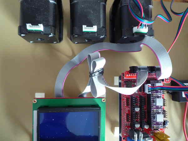
The picture was taken a little later when I had removed the X and Y stepper connectors. Btw: The X driver is closest to the power connector, then comes the Y driver and the last of the three is the Z driver.
Then comes the big moment: power on!
If everything works you will be greeted by the following screens:
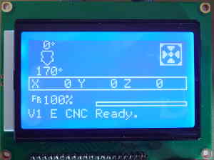
One push on the selector/push-button (below the LCD screen on the right) gives:
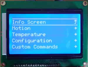
Now we can proceed to select individual stepper motors and move them a little. I found this interface quite intuitive and just firing up a stepper to make a small move is enough to ensure that the tuning for that stepper-driver can be performed. Do this one axis at a time to prevent prolonged and possibly too high currents in any one stepper.
The sensitivity to movements of the potentiometer was quite high. I was unable to achieve more than 15 mV accuracy. Still, it should be close enough. I also noted that the fins on the drivers get quite hot. Almost too hot to touch. I will have to reduce the maximum current even more once the CNC is complete, such that the steppers can drive the CNC easily, but no more.
I then proceeded to see if movements selected by the LCD interface would turn the steppers as expected. That turned out not so well. Both the Y and Z steppers started vibrating instead of turning. Only the X stepper turned smoothly. More about this in the next post.