Faulty wires
In the last post I described that the X-axis stepper worked just fine, but the Y and Z axes steppers vibrated instead of turning.
You may remember that one of the steppers that I originally received was damaged and I had to replace it. The shop did this without problems. However now it almost looks as if I have two more defective steppers. Hmm.
Since one stepper was fine, I first removed the connectors for the Y and Z steppers and checked operation of the Y and Z drivers with the X-axis stepper. As I hoped (and expected) the drivers for the Y and Z steppers worked fine. That was a relief as this would have been a more serious fault. But the RAMPS board and the drivers are fine.
Now I had to find out if the steppers are the problem. I swapped the connecting wires for the Y and Z steppers in turn with the wire used for the X stepper. And to my surprise the Y and Z steppers worked fine.
Thus it could only be the connecting wire for the Y and Z axes.
I tested the wires with an Ohm meter for proper end-to-end connections, and the wires are fine. Then I checked for short circuits, but again the wires checked out fine.
That of course puzzled me, how can the wires be fine, but not work?
Then I noticed something: a cross over of two wires. And the crossover was in the working set. The two other (faulty) sets did not have the crossover!
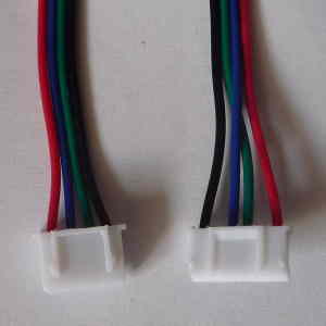
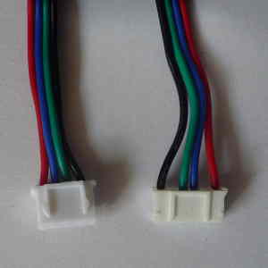
Ah!
How this is possible I do not know. The wires come with the stepper motors. So this must be a manufacturer error.
Anyway, it is simple to make the crossover myself, so I won’t bother with claiming a replacement set (that would probably take a couple of weeks).
Here is the result:
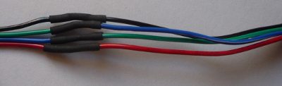
And I am happy to report that all axes now work as expected!
There are two things left to do before I will order the other (hardware) parts for the CNC:
First I have to be able to create a design and generate the G-code for it, and second the V1-Engineering Marlin variation must be configured to use lead screws on all axis (instead of a belt on the X and Y). It may even be necessary (or advantageous) to go back to the normal Marlin driver and fork from there. That remains to be seen.
My test approach will be simple: Since 8mm of travel is one revolution of the stepper, a design consisting of a rectangle of 32 mm x 16 mm (X by Y), has to result in 4 revolutions of the X axis and 2 of the Y axis. A clearance space of 8 mm will allow a checkout of the motion along the Z axis.
Btw, the X-axis = length, Y-axis = width, Z-axis = height.