Flaps design
This is how I tried to design the flaps, first I printed the wing profile in scale 1:1. On this I guesstimated a spot where the hinge of the flaps would need to be placed. I guessed this based on the pictures of the flaps on the real plane.
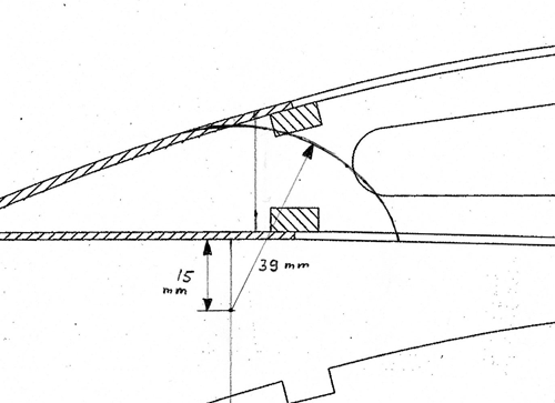
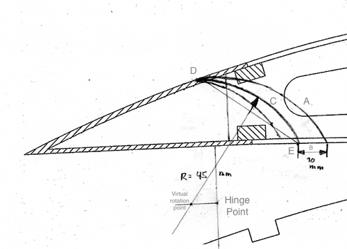
Initially a hinge point slightly back of the line where the ailerons are separated and 15mm below the wing was chosen. Then the smallest distance to the top of the wing at that point was measured at 39mm. A circle segment was drawn from the top of the wing to the bottom side of the wing.
If this circle segment is the separation of flap and wing, then a rotation at the hinge point will cause the flap to slide along the wing. But there will be no separation. And that separation is essential for the slotted flaps. To achieve a separation, a point was chosen at the bottom of the wing, 10mm back of the circle segment:
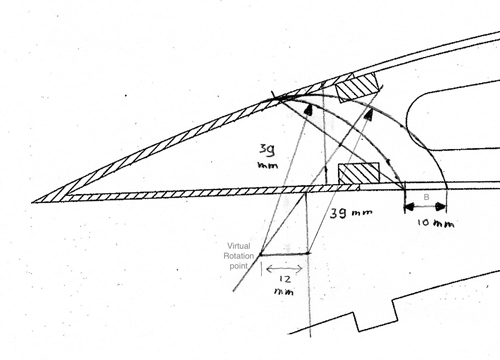
From that point on the bottom of the wing a line was drawn to the top of the wing where the circle segment touches. In the middel of that line another line was drawn at a right angle. At the same distance from the bottom of the wing in this new line a virtual hinge point was created. And with that as the center of a circle segment another segment was drawn with the same radius as before.
If this new circle segment line is used as the separation of flap and wing, but the original hinge point is used, then a flap movement is created that pulls the flap away from the wing while at the same time angling it downward. A gap, the ‘slot’ is created.
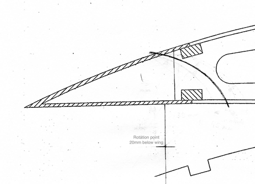
However I was by this time dissatisfied with the shape of the front of the flap. Its much too steep. To lower the angle the original hinge point must be moved further below the wing. This distance was increased to 20mm:
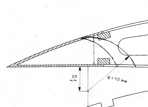
Then the same process as before was used to create a new offset-circle segment. In the figure below this is draw between the two existing circle segments.
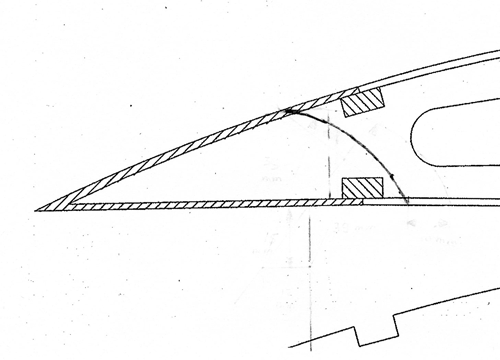
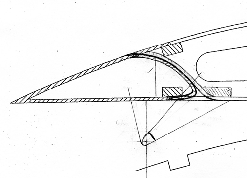
Removing the lines no longer needed:
This is much more to my liking, so an attempt was made to flow the lines a bit and create a flap drawing from this:
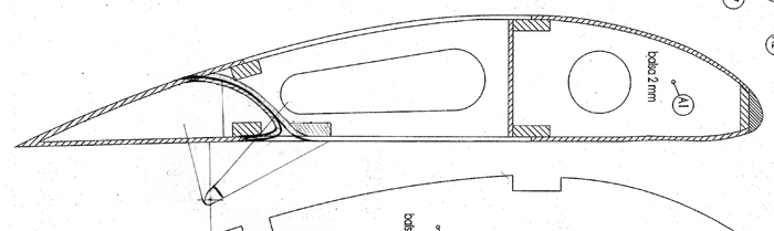
Looking at the whole profile:
Next I printed the scan out, and cut out the flap profile. This allows me to play around a bit with the hinge point and see what happens with different hinge points
Here are a couple of pictures using the original hing point which seems to work fine. Btw I am holding a needle point at the hinge location as a surrogate hinge. (the black shape that is visible)
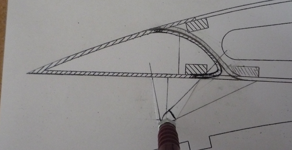
Now at about 15 degree angle, a small channel opens up between wing and flaps:
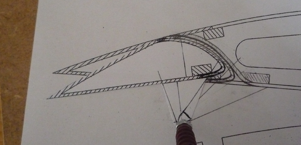
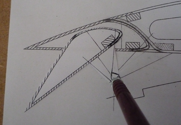
At 45 degrees the channel becomes quite big:
And one with an alternate position of the hinge point:
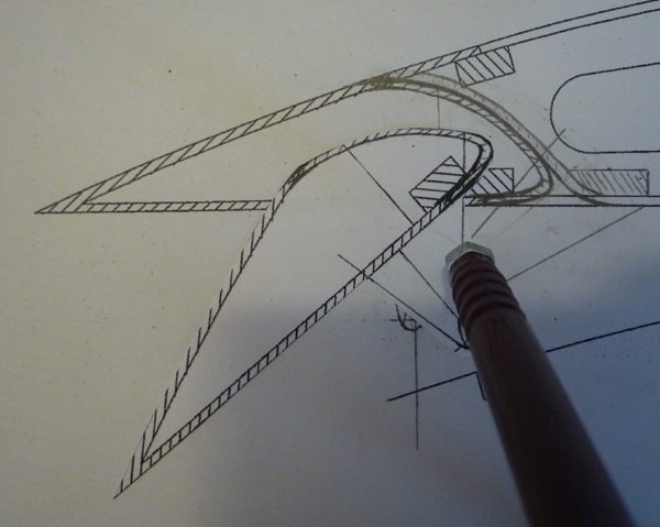
Given the shape of the channel, I prefer the original hinge point as that is more in line with the slotted flaps as seen in the wind-channel video’s (see previous post).
So… I am reasonably pleased with this. But I think it can be improved slightly resulting in a smoother top of the flap and a slightly smaller flap. More in line with the real plane. However the same approach to designing will be used.