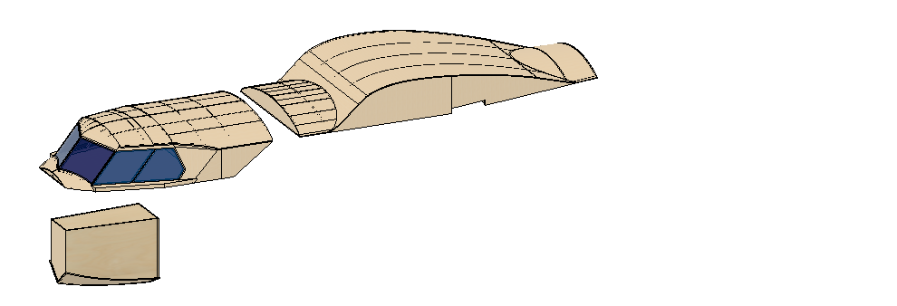
Nacelle design completed (more or less)
This week I finished the nacelle. The main body is complete, but some smal bits (fences, cooler adapters) still have to be added.
Total weight so far, as reported by Fusion360 is about 85 grams. Which I think is acceptable.
I decided against using CFRP for the cowling because of weight. From doing some testing with the design for the floats, CFRP is about 10 times as heavy as balsa wood. But savings in the form of thickness are just about 5 times. Hence the weight of a part in CFRP as opposed to balsa is still twice as heavy.
Where structural issues are important it makes sense to use CFRP, but I see no such issues with the nacelles, and hence will do them in balsa entirely. (Well, including some bits of other wood types where needed)
The pictures:
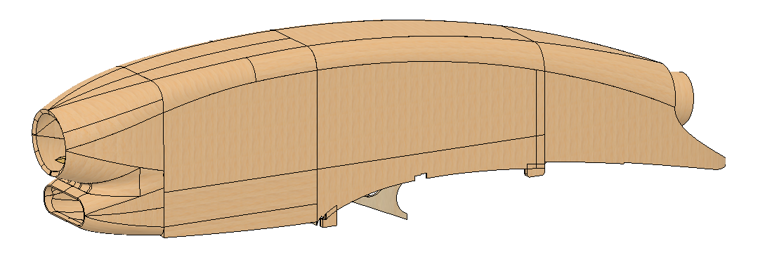
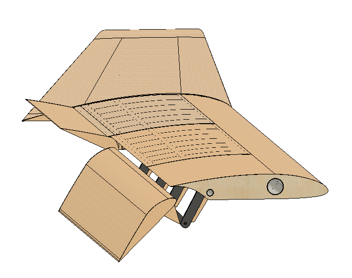
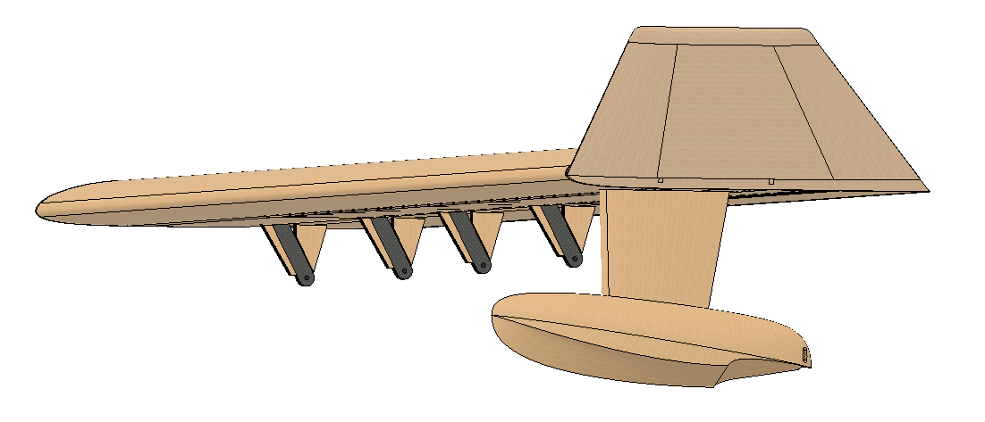
As you can see, the air inlet and propeller adapter will be CNC-ed out of solid balasa. The entire nacelle is hollow thus air can flow through for the cooling of the engine.
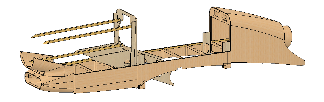
The engine bay is visible when removing the cowling. An axis extender will probably be necessary for most engines. Also, the engine bay is not complete, some addition struts or other structural improvements will be added when the engine has been selected.
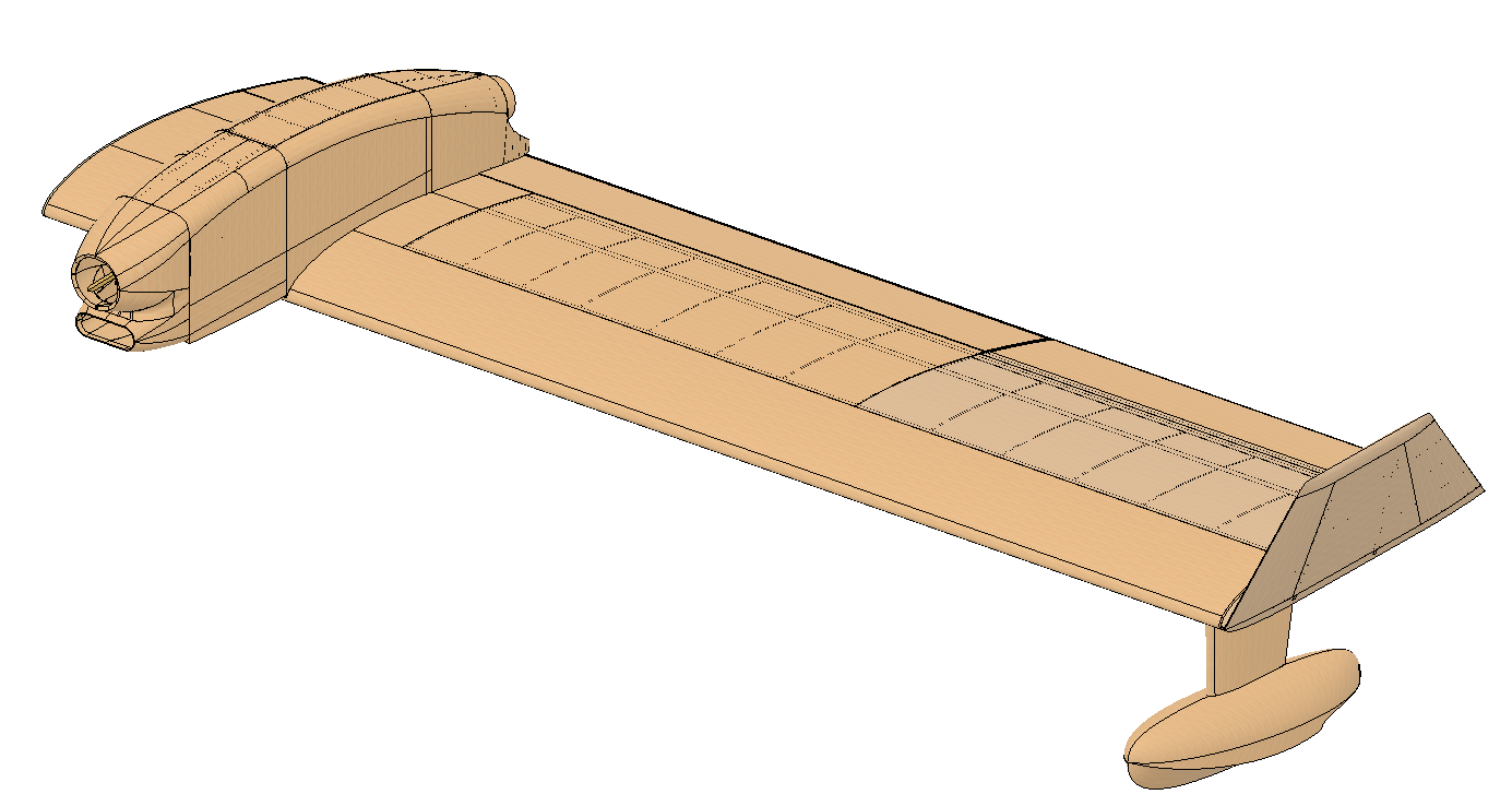
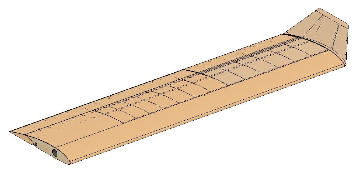
The whole wing, but without the nacelle adapter, fences and cooler.
Wing progress
After the fuselage, work has progressed on the wing:
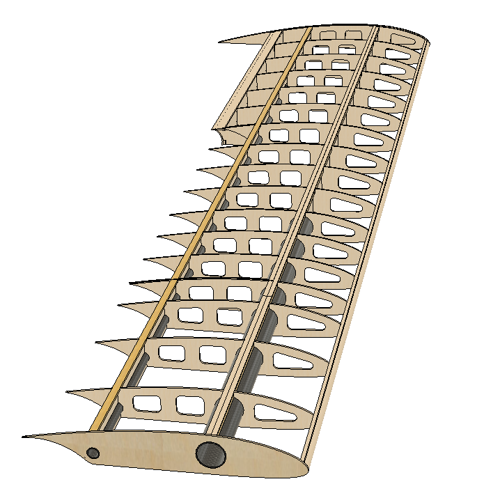
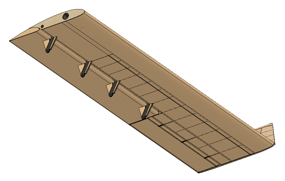
The offset flaps are seen quite clearly. The flaps extend (as in the image) to -45 degrees. The ailerons are placed at their max of +25 degrees. They can move to -45 degrees also.
The float gave the most problems so far, though the nacelle will probably also be quite difficult. At least the experience gained by the float can be used.
I am creating a few rules for myself to manage the Loft command:
- Try not to use rails. Rails seem to act as attractors for every point in the face or body that is lofted. Which is fine when lofting, say, a tent. But is horrible when trying to extrapolate a body shape between two formers.
- Try to avoid splines, but if splines cannot be avoided, use the same number of spline control points in each spline (profile or rail)
Once a face can be constructed the ‘thicken’ command is not always useable. Though I am not sure yet, it may be related to the radius of curvature. When this is smaller than the thicken value, the thicken may fail. As I said, I am not sure of this yet.
On to the nacelles…
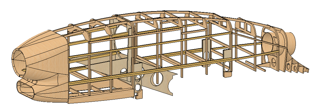
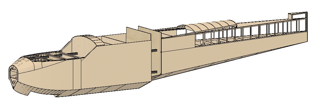
Fuselage v1.0
The fuselage v1.0 is now ready.
And when I say “ready” I do not literally mean “completely done, nothing left to do”. But the fuselage as such should indeed be ready. The points that will need some attention in the future are:
- Connecting the cabin.
- Connecting the wing-dome.
- Connecting vertical stabelizer.
- Include a base for the RC installation
- Nose wheel mounting.
- Main gear mounting.
It is also likely that some issues will turn up when building the thing that may require additional or redesigned parts.
These points will be addressed later, next on the list are the wing, nacelles & floats.
So far, Fusion360 reports a total weight of 1685 grams, and a center of gravity at just about the leading edge of the wings. Not too bad I think. Even if the weight is a tad high for my taste. There is some overenginering going on, so it may be possible to save a little. An optimistic guess would be 10%. However that is an issue for later, if the total weight is getting way past the target.
Another status update
It has been some time since the previous update, so just to let everybody know, I am still at it ;-)
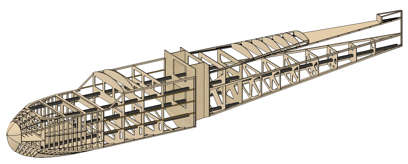
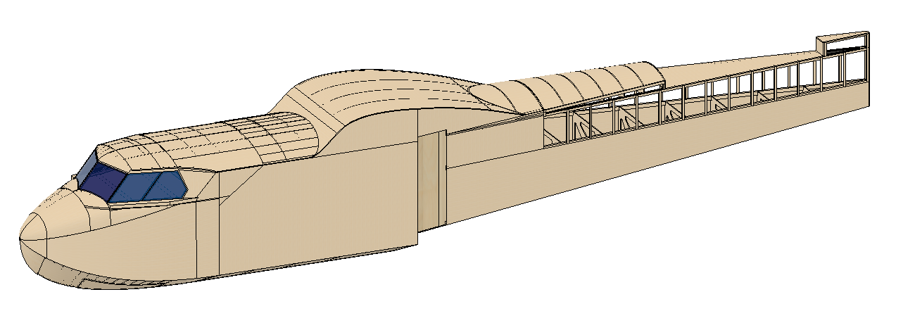
This is how the fuselage components look today, frame and longerons only:
This is how the formers look:
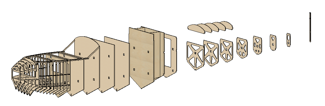
And this is both the above together:
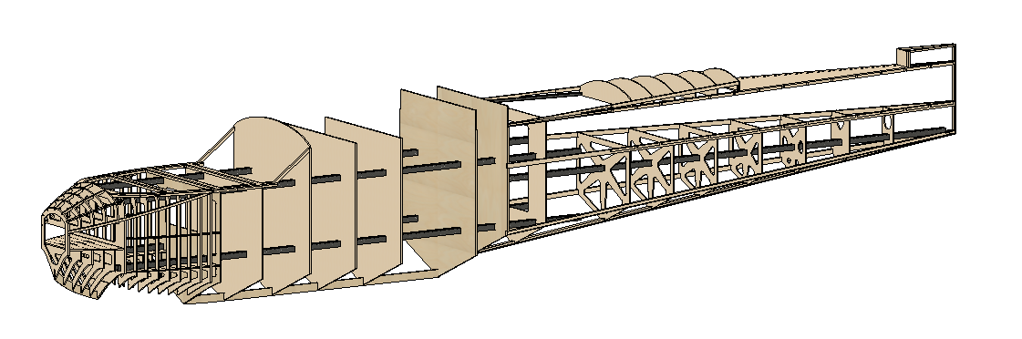
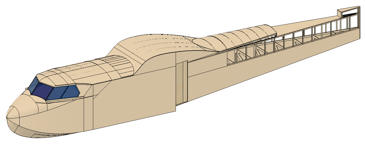
The above with planking:
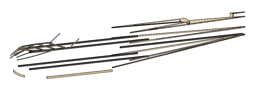
The separate components:
And all together:
What I learned so far in fase 2:
- It is very easy to lose sight of component complexity. It is very easy to create a perfectly fitting component that is impossible to make.
- Another variant on the above is creating components that take a long time to make or require multiple orientations to be machined.
- Then there is the case of perfectly fitting components, but impossible to assemble.
- Next up: using base materials that are too expensive. I discovered that I was using a rod with a length of 1.05m, which is not a good idea since that means a standard length of 1m does not fit and a 2m tube must be cut down to 1.05m. Leaving 95cm of waste. With a price of, say, USD15 per meter, and using 4 of those rods, that cost roughly 60USD too much. Much better to change the design and use 1m rods.
- Perfectionism: the bane of every design… especially CAD/CAM designs. I have now adopted the approach that not all components will be completely formed on the CNC, but rather many of them will need additional work before or after assembling (glueing).
Well that is it for now.
Btw: This did sharpen my design goals. I do want the plane asap, but I also like building. Thus creating a “builders plane” is a double win to me. Just creating a perfect design that is simply assembled in an afternoon, especially if that means a much higher price tag, is not my kind of thing.
Oh, and I have not finished the CNC machine yet… bummer.
Phase 1 completed
A look at the end result of phase 1:
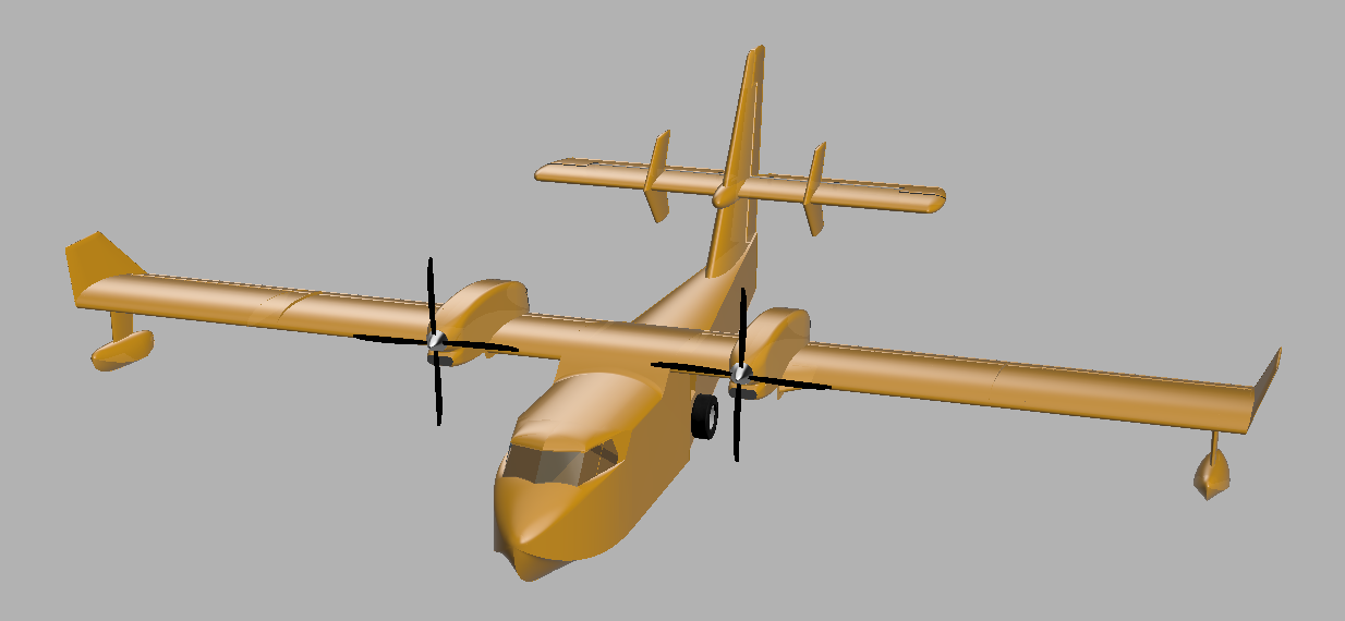
All faces have been defined, resulting in a complete looking model. True, I did not put any ‘make-up’ on the model, so it looks rather unassuming. But the purpose of phase 1 was to fully define all faces that will be used in phase 2 for sizing/cutting the internal structure.
And as an aside, it was also intended to familiarize myself with Fusion 360.
To see it from all sides, see this video. (It does contain a few “print-throughs” and glitches)
With phase 1 out of the way, its time to finish the CNC macine. Once that is done phase 2 will be started. Though I have to say that the shed is quite cold now… so I may occasionally be unable to resist the temptation to stay warm and start on phase 2 before the CNC machine is fully operational.
Just in case you are interested, the CNC build is blogged about on http://starbase55.com/cnc.